Software Engineering

What is Software Process?

A software process is a set of related activities that leads to the production of a software product. These activities may involve developing software from scratch in languages like Java or C. However, modern business applications often extend existing systems or integrate off-the-shelf software components.

Four Activities Fundamental to Software Engineering

  1. Software specification: The functionality and constraints of the software are defined.
  2. Software design and implementation: The software is produced according to the specification.
  3. Software validation: Ensures the software meets the customer's needs.
  4. Software evolution: The software evolves to meet changing requirements.

These activities are part of all software processes, though each involves complex sub-activities such as requirements validation and unit testing. Supporting activities like documentation and configuration management are also vital.

Process descriptions may also include:

  • Products: Outcomes of a process activity
  • Roles: Responsibilities of the people involved
  • Pre- and post-conditions: Statements that are true before and after a process activity

Software processes are complex and depend on human judgment. There is no single ideal process — most organizations adapt processes to their systems and people. For critical systems, a structured process is used, while for business systems, flexibility is key.


Software processes are categorized as either plan-driven or agile. Plan-driven processes are planned in advance, while agile methods emphasize adaptability.


Process improvement can be achieved through standardization, which enhances communication, reduces training time, and supports automation.

A software process model is a simplified representation of a software process, showing certain perspectives like activities or roles. These models serve as frameworks for understanding and improving software development.


The main process models include:


  1. The Waterfall Model: Divides development into phases such as requirements, design, implementation, and testing.
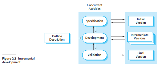
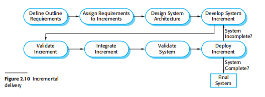
  2. Incremental Development: Builds the system in a series of versions, each adding functionality.
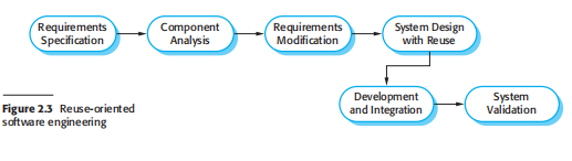
  3. Reuse-Oriented Software Engineering: Focuses on integrating existing reusable components.

Large systems often combine different models. For instance, core requirements might use a waterfall approach, while user interfaces are developed incrementally.

Software Process Models Diagram

Figure 2.1: The Waterfall Model


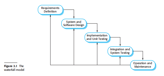
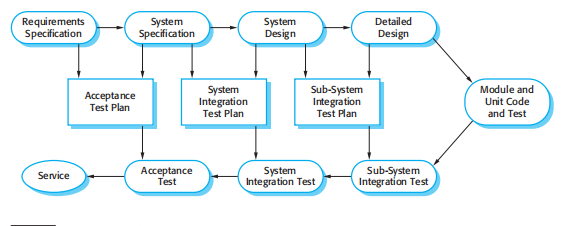
The first published model of the software development process was derived from more general system engineering processes (Royce, 1970). This model is illustrated in Figure 2.1. Because of the cascade from one phase to another, this model is known as the ‘waterfall model’ or software life cycle. The waterfall model is an example of a plan-driven process—in principle, you must plan and schedule all of the process activities before starting work on them.


Principal Stages of the Waterfall Model Reflect the Fundamental Development Activities:


  1. Requirements analysis and definition: The system’s services, constraints, and goals are established by consultation with users and documented in detail.
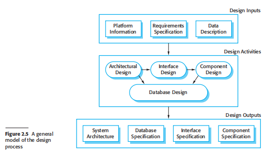
  2. System and software design: Requirements are allocated to system components, defining architecture and software abstractions.
  3. Implementation and unit testing: The design is realized through coding, and each unit is tested to meet specifications.
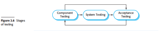
  4. Integration and system testing: Components are integrated and tested as a complete system to ensure requirements are met.
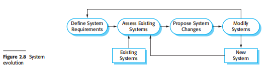
  5. Operation and maintenance: The system is deployed and maintained; errors are corrected, and enhancements are made as new requirements arise.

Each phase produces documentation that is reviewed and approved before the next phase begins. However, in practice, feedback loops occur — issues in design may lead to revisiting requirements, and testing can reveal design flaws. This iterative reality makes the process more dynamic than a simple linear flow.


The waterfall model is consistent with engineering discipline — structured, document-driven, and predictable. Its downside lies in inflexibility; adapting to changing requirements can be costly once stages are locked.


This model works best when requirements are stable and well understood from the start. It’s still widely used because it aligns with standard project management practices and offers visibility through documentation.


Variants like formal system development introduce mathematical precision to improve safety and reliability, making it suitable for mission-critical or security-critical systems.

Based on the idea of developing an initial implementation, exposing this to user comment, and evolving it through several versions until an adequate system has been developed (Figure 2.2). Specification, development, and validation activities are interleaved rather than separate, with rapid feedback across activities.


Incremental software development, a key part of agile methodologies, is often superior to the waterfall model for business, e-commerce, and personal systems. It mirrors how we naturally solve problems — iteratively improving and adjusting with feedback.


Each increment of the system includes essential customer functionality. Early increments focus on the most important requirements, allowing early evaluation and adjustment before full completion.


Incremental development offers three main advantages over the waterfall model:

Incremental Development Model

Figure 2.2: Incremental Development

  1. The cost of accommodating changing requirements is reduced, as less documentation must be redone.
  2. Customer feedback is easier to obtain since users can evaluate partial implementations.
  3. Useful software is delivered earlier, even before all functionality is complete.

Incremental development is now the most common approach to system development — whether plan-driven, agile, or hybrid. Early increments may be planned in advance, while later ones adapt to user priorities.


From a management perspective, two key challenges exist:


  1. Process visibility: Without formal deliverables for each version, tracking progress can be difficult.
  2. Architectural degradation: As increments accumulate, system structure may degrade unless time is devoted to refactoring.

These challenges are most acute in large, complex systems involving multiple teams.Incremental development can also combine with staged deployment, where real user interaction provides valuable feedback.

Reuse-Oriented Software Engineering Diagram

Figure 2.3: Reuse-oriented Software Engineering

In reuse-oriented software engineering, systems are constructed using existing components rather than developing everything from scratch. This approach emphasizes efficient assembly over original design.


  1. Component analysis: Identify reusable components that can meet system requirements.
  2. Requirements modification: Adjust system requirements to align with available components.
  3. System design with reuse: Integrate selected components into a cohesive system architecture.
  4. Development and integration: Develop missing parts and integrate all reusable and new components into the final product.

Types of software components used in reuse-oriented processes:


  1. Web services developed according to open service standards and accessible remotely.
  2. Object collections packaged for frameworks such as .NET or J2EE.
  3. Standalone software systems configured for specific operating environments.

Reuse minimizes effort, cost, and risk while accelerating delivery. However, it may require compromises in requirements and reduce control over future updates when external components change. For detailed discussions, see Chapters 16–19.

Real software processes are interleaved sequences of technical, collaborative, and managerial activities with the overall goal of specifying, designing, implementing, and testing a software system. Software developers use a variety of different software tools in their work. Tools are particularly useful for supporting the editing of different types of document and for managing the immense volume of detailed information that is generated in a large software project.


The four basic process activities of specification, development, validation, and evolution are organized differently in different development processes. In the waterfall model, they are organized in sequence, whereas in incremental development they are interleaved. How these activities are carried out depends on the type of software, people, and organizational structures involved. In extreme programming, for example, specifications are written on cards. Tests are executable and developed before the program itself. Evolution may involve substantial system restructuring or refactoring.

2.2.1 Software Specification

Software specification or requirements engineering is the process of understanding and defining what services are required from the system and identifying the constraints on its operation and development. Errors at this stage inevitably lead to later problems in system design and implementation.


The requirements engineering process aims to produce an agreed requirements document that specifies a system satisfying stakeholder needs. Requirements are usually presented at two levels of detail — high-level for customers and detailed for developers.


There are four main activities in the requirements engineering process:


  1. Feasibility study: Estimates whether identified user needs can be met using current technology and within budget.
  2. Requirements elicitation and analysis: Derives system requirements through discussions, observation, and modeling.
  3. Requirements specification: Translates gathered information into a clear requirements document.
  4. Requirements validation: Checks requirements for consistency, realism, and completeness.
Software Specification Diagram

Figure 2.4: The Requirements Engineering Process

2.2.2 Software Design and Implementation

The implementation stage converts a system specification into an executable system. It involves both design and programming, and often overlaps when using incremental approaches.


A software design describes the system’s structure, data models, interfaces, and algorithms. Designers iteratively refine the design with constant backtracking to improve structure and correctness.


Feedback is an essential part of the design process — stages are interleaved, not strictly sequential.


  1. Architectural design: Defines the overall system structure and module relationships.
  2. Interface design: Specifies interfaces between components, allowing independent development.
  3. Component design: Defines internal operations of each system module.
  4. Database design: Describes how data will be organized and stored in the system.
Software Design and Implementation

Figure 2.5: A GeneraL Model of the Design Process

2.2.3 Software Validation

Software validation ensures that a system both conforms to its specification and meets customer expectations. Program testing is the main validation technique, supported by reviews and inspections.


Testing is not a single-step activity; it proceeds in multiple stages:


  1. Development testing: Tests individual components using automated tools.
  2. System testing: Verifies that integrated components work together and meet system requirements.
  3. Acceptance testing: Validates the final product with real user data before deployment.
Software Evolution Diagram

Figure 2.6: Stages of Testing

2.2.4 Software Evolution

The flexibility of software makes it easier and cheaper to modify compared to hardware. Over time, software evolves as new requirements emerge and technologies change.


Historically, development and maintenance were treated separately, but now software engineering is viewed as an evolutionary process where systems are continually updated and improved throughout their lifetime.

Software Validation Diagram

Figure 2.7: Testing Phases in a Plan-Driven Software Process

Change is inevitable in all large software projects. The system requirements change as the business procuring the system responds to external pressures and management priorities change. As new technologies become available, new design and implementation possibilities emerge. Therefore, whatever software process model is used, it is essential that it can accommodate changes to the software being developed.


Change adds to the costs of software development because it usually means that work that has been completed has to be redone. This is called rework. For example, if the relationships between the requirements in a system have been analyzed and new requirements are then identified, some or all of the requirements analysis has to be repeated. It may then be necessary to redesign the system to deliver the new requirements, change any programs that have been developed, and re-test the system.


There are two related approaches that may be used to reduce the costs of rework:


  1. Change avoidance: Where the software process includes activities that can anticipate possible changes before significant rework is required. For example, a prototype system may be developed to show some key features of the system to customers. They can experiment with the prototype and refine their requirements before committing to high software production costs.
  2. Change tolerance: Where the process is designed so that changes can be accommodated at relatively low cost. This normally involves some form of incremental development. Proposed changes may be implemented in increments that have not yet been developed. If this is impossible, then only a single increment (a small part of the system) may have to be altered to incorporate the change.

The notion of refactoring, namely improving the structure and organization of a program, is also an important mechanism that supports change tolerance. This topic is explored further in Chapter 3, which covers agile methods.

System Evolution

Figure 2.8: System Evolution

2.3.1 Prototyping

Prototype Development

Figure 2.9: The Process of Prototype Development

A prototype is an initial version of a software system that is used to demonstrate concepts, try out design options, and find out more about the problem and its possible solutions. Rapid, iterative development of the prototype is essential so that costs are controlled and system stakeholders can experiment with the prototype early in the software process.


A software prototype can be used in a software development process to help anticipate changes that may be required:


  1. In the requirements engineering process, a prototype can help with the elicitation and validation of system requirements.
  2. In the system design process, a prototype can be used to explore particular software solutions and to support user interface design.

System prototypes allow users to see how well the system supports their work. They may get new ideas for requirements, and find areas of strength and weakness in the software. They may then propose new system requirements. Furthermore, as the prototype is developed, it may reveal errors and omissions in the requirements that have been proposed.


A system prototype may be used while the system is being designed to carry out design experiments to check the feasibility of a proposed design. For example, a database design may be prototyped and tested to check that it supports efficient data access for the most common user queries.


A process model for prototype development is shown in Figure 2.9. The objectives of prototyping should be made explicit from the start of the process. These may be to develop a system to prototype the user interface, to validate functional system requirements, or to demonstrate feasibility.

Incremental Delivery

Figure 2.10: Incremental Delivery

Developers are sometimes pressured by managers to deliver throwaway prototypes, particularly when there are delays in delivering the final version of the software. However, this is usually unwise:


  1. It may be impossible to tune the prototype to meet non-functional requirements, such as performance, security, robustness, and reliability.
  2. Rapid change during development means that the prototype is undocumented, making long-term maintenance difficult.
  3. Frequent changes degrade the system structure, increasing maintenance costs.
  4. Quality standards are often relaxed for prototype development.

Prototypes do not have to be executable to be useful. Paper-based mock-ups of the system user interface can be effective in helping users refine an interface design and work through usage scenarios. These are very cheap to develop and can be constructed in a few days. An extension of this technique is a Wizard of Oz prototype where only the user interface is developed. Users interact with this interface but their requests are interpreted manually.

2.3.2 Incremental Delivery

Incremental delivery (Figure 2.10) is an approach to software development where some of the developed increments are delivered to the customer and deployed for use in an operational environment. In this process, customers identify in outline the services to be provided by the system, prioritizing which services are most important. Several delivery increments are then defined, each providing a subset of system functionality. The highest-priority services are implemented and delivered first.


Once the system increments have been identified, the requirements for the services to be delivered in the first increment are defined in detail and that increment is developed. During development, further requirements analysis for later increments can take place, but requirements changes for the current increment are not accepted.


Once an increment is completed and delivered, customers can put it into service, allowing early delivery of part of the system functionality. This helps customers clarify their requirements for later increments. As new increments are completed, they are integrated with existing ones so that the system functionality improves with each delivery.

Incremental delivery has several advantages:


  1. Customers can use early increments as prototypes and gain experience that informs requirements for later increments. These are part of the real system, so there is no re-learning when the final version arrives.
  2. Customers gain value early — the first increment satisfies their most critical requirements, allowing immediate software use.
  3. The process retains the flexibility of incremental development, making it easier to incorporate changes.
  4. High-priority services are delivered and tested first, reducing the risk of encountering failures in the most critical system areas.

However, there are challenges with incremental delivery:


  1. Many systems require shared foundational facilities. Because requirements are defined incrementally, it can be difficult to identify common facilities early.
  2. Iterative development is hard for replacement systems, as users expect all old functionalities and may resist incomplete new systems.
  3. Incremental processes conflict with procurement models that require a full specification before contracting — common in large organizations like government agencies.

Some systems are not suited for incremental development — for instance, very large distributed systems, embedded systems tied to hardware, or safety-critical systems that need complete requirement analysis for risk validation.


To gain some benefits of incremental development in these cases, teams may iteratively develop a prototype to experiment with system requirements and design. The insights gained then guide the creation of definitive system requirements.

2.3.3 Boehm’s Spiral Model

A risk-driven software process framework, the Spiral Model, was proposed by Barry Boehm (1988). Illustrated in Figure 2.11, it represents the software process as a spiral rather than a simple sequence of activities. Each loop in the spiral corresponds to a phase — such as feasibility, requirements, design, or development — integrating change avoidance with change tolerance. It assumes that changes stem from project risks and explicitly includes risk management to minimize them.


Each loop in the spiral is divided into four key sectors:

Boehm’s Spiral Model

Figure 2.11: Boehm’s Spiral Model of the Software Process

  1. Objective setting: Define specific objectives for that phase, identify constraints, create management plans, and outline potential risks with alternative strategies.
  2. Risk assessment and reduction: Analyze each project risk in detail and take preventive steps — for example, developing a prototype to mitigate uncertain requirements.
  3. Development and validation: Choose the best development model for the situation — e.g., throwaway prototyping for UI risks, formal methods for safety, or waterfall for integration concerns.
  4. Planning: Review project progress and decide whether to proceed with the next loop of the spiral, creating detailed plans for the next iteration.

The Spiral Model’s major distinction from other models is its explicit recognition of risk. Each cycle starts by defining objectives and constraints, then exploring alternatives to mitigate risks. These risks are resolved through information-gathering, prototyping, or simulation before moving to development.

Once risks are assessed, the project proceeds with development followed by planning for the next iteration. Here, “risk” simply refers to anything that can go wrong — such as unreliable compilers, inefficient object code, or poor integration. Risk management, essential to project success, reduces potential schedule delays and cost overruns. This is explored further in Chapter 22.

The Rational Unified Process (RUP) (Krutchen, 2003) is an example of a modern process model that has been derived from work on the UML and the associated Unified Software Development Process (Rumbaugh, et al., 1999; Arlow and Neustadt, 2005). It is a good example of a hybrid process model that brings together elements from all the generic process models, illustrates good practice in specification and design, and supports prototyping and incremental delivery.


The RUP recognizes that conventional process models present a single view of the process. In contrast, the RUP is described from three perspectives:

  1. A dynamic perspective, which shows the phases of the model over time.
  2. A static perspective, which shows the process activities that are enacted.
  3. A practice perspective, which suggests good practices to be used during the process.

Most descriptions of the RUP attempt to combine the static and dynamic perspectives in a single diagram (Krutchen, 2003). This makes the process harder to understand, so separate descriptions of each perspective are often clearer.


The RUP is a phased model that identifies four discrete phases in the software process. However, unlike the waterfall model where phases are equated with process activities, the RUP phases are more closely related to business rather than technical concerns. These are:

  1. Inception: The goal of the inception phase is to establish a business case for the system. All external entities (people and systems) interacting with the system are identified, and these interactions are used to assess the system’s contribution to the business.
  2. Elaboration: The goals of the elaboration phase are to develop an understanding of the problem domain, establish an architectural framework, develop the project plan, and identify key project risks.
  3. Construction: The construction phase involves system design, programming, and testing. Parts of the system are developed in parallel and integrated during this phase.
  4. Transition: The final phase of the RUP is concerned with moving the system from development to the user community and ensuring it works in a real environment.
Rational Unified Model

Figure 2.12: Phases in Rational Unified Process

Iteration within the RUP is supported in two ways: each phase may be enacted iteratively with results developed incrementally, and the entire set of phases may also be enacted incrementally, as shown by the looping arrow from Transition to Inception in Figure 2.12.


The static view of the RUP focuses on the activities (workflows) that take place during development. There are six core process workflows and three supporting workflows. The RUP is designed alongside UML, so its workflow descriptions are oriented around UML models such as sequence and object models.


The advantage of presenting dynamic and static views is that RUP workflows are not tied to specific phases — in principle, all workflows may be active at all stages. Early phases emphasize business modelling and requirements, while later phases focus on testing and deployment.


The practice perspective on the RUP describes good software engineering practices recommended for system development. Six fundamental best practices are:

Static Workflow Rational Unified Model

Figure 2.13: Static Workflows in the Rational Unified Process

  1. Develop software iteratively: Plan system increments based on customer priorities and develop in manageable stages.
  2. Manage requirements: Explicitly document and track customer requirements. Analyze change impact before acceptance.
  3. Use component-based architectures: Structure system architecture into reusable and modular components.
  4. Visually model software: Use graphical UML models to show static and dynamic system views.
  5. Verify software quality: Ensure software meets organizational quality standards through testing and reviews.
  6. Control changes to software: Manage software modifications with change and configuration management systems.

The RUP is not suitable for all development types (e.g., embedded systems), but it effectively combines elements from the three generic process models. Its key innovations include separating phases from workflows and recognizing deployment as an essential part of the process. Phases are dynamic and goal-oriented, while workflows are static and technical, supporting all stages of development.